I have but two simple complaints about my new Vespa Grantourismo. One, that the slightest overfilling of the gas tank sucks fuel into the intake track. And second, that you don’t get any auditory clue when your turn indicators are up and blinking.
Leaving your blinkers on accidentally sends the wrong signal to vehicles and can easily get your arse run over. There’s the dash lights, but the attentions of riding keep my eyes off the gauges for the most part. I’ve taken to over-canceling the switches and more than once I’ve canceled my turn before actually executing it. I had the same problem in my 1979 Vespa P200E. My fix then, as it is now, was to wire a simple buzzer into the turn indicator electrics. For about $5 in parts, I’ve added a nice level of riding safety.
I’d wired a set of these before, but thanks to this post on ModernVespa, I found slightly better way to wire them. The circuit is actually pretty simple. On the GT, I was able to wire the whole thing through just the body openings for the indicator lenses and the opening behind the horn cover — that is to say, I didn’t need to remove the glove box or the rear cover to the leg shield.
Supplies
- 1 – Piezo Buzzer. Radio Shack part # 273-080
- 2 – Diodes. Radio Shack part # 276-1101
- 4ft – Red 18 gauge wire
- 2ft – Black 18 gauge wire
- 1 – In-line fuse holder with 20A fuse
- 1 – cable tie
Tools
- Phillips screwdriver, medium and large
- Wire clippers (a wire stripper is also a good idea, much easier)
- Soldering iron/micro-torch and solder
- Hot glue gun
Preparation
- Remove the four philips-head screws in the floor board to reveal the battery.
- Disconnect the negative (black) battery terminal and lay it aside so that it can’t accidentally touch the terminal again.
- Remove the single philips-head screw from the base of each turn indicator lens and pull the lens forward and out of the scooter body.
- Disconnect the wire at the connecter under the rubber boot.
- Remove the indicator lens assemblies from the body completely and set them aside.
- Remove the single philips-head screw from the top corner of the left side knee pad and remove.
Wiring and mounting
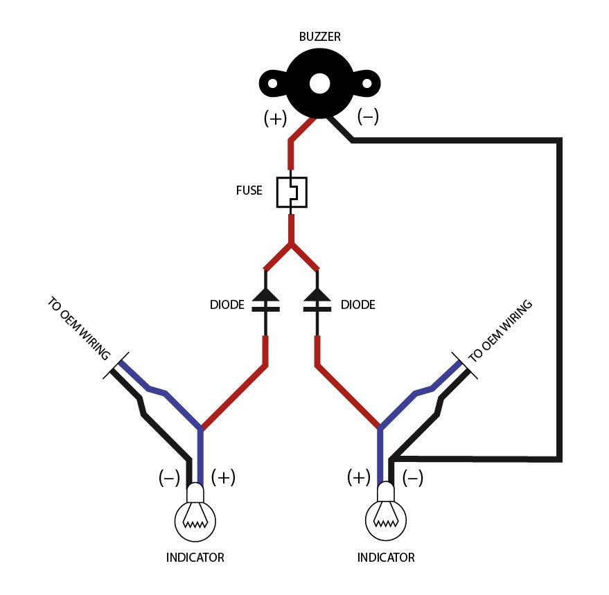
What we’re creating here is essentially two one-way circuits that share a common ground wire. The diodes let us wire both lenses to a single buzzer. Without the diodes, current would backtrack to the other indicator light and you’d get both lights at once, which sort of defeats the whole purpose. The alternative would be to wire a buzzer into each light, but that’s a waste since about $0.65 worth of electrical parts lets us have a much simpler circuit.
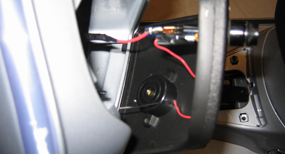
I mounted and wired the components as I went. Starting with the fuse, I drilled a 1/2″ hole in the knee pad to accept the fuse holder. You need not do it this way. This was simply the fuse holder I had left over from my old Vespa. I mounted it externally, that way if I do blow a fuse I don’t have to take anything apart to swap it. This left side pad panel is ideal for these kinds of mods since there’s nothing underneath it. The right side pad panel houses the coolant reservoir, so best not to crowd anything in there if you don’t have to. After attaching the fuse holder, I hot-glued the buzzer to the backside of the panel. Even though it’s on the inside of the panel, it’s plenty loud to be heard over engine and road noise and even when wearing a full-face helmet.
When wiring the diodes, keep in mind that they are directional and that direction is indicated by the stripe on the barrel of the diode. In the case of this circuit, you can actually face the two diodes in the same direction and solder their downstream leads together. Make sure the stripe is pointed toward the buzzer and you’re golden. Then run two separate red leads, one from each of the separate upstream leads of the diodes. These will connect to the positive (colored) wires on the OEM indicator light wiring. You’ll also need to extend a black ground wire. This will connect into the black ground wire in the OEM wiring, but it need only connect on one side. It’s also a really good idea to use a multi-meter to check for continuity as you go. Or at the very least, be sure to check your assembled wiring before you install it into the scooter. Also remember that since you’ve got diodes, the polarity of your testing wires will actually matter.
Splicing into the OEM wiring is not too tricky. Peel back the black tape the covers the wires until you’ve got a good 3″ of wire away from the connector. You’ll be splicing both wires on one side, and only the “hot” or colored wire on the other. Be sure to leave yourself enough room so that the rubber boot can slide back off of the connector enough to connect and disconnect the lens without putting stress on your splices. Insulate everything thoroughly with shrink wrapping or electrical tape before reassembling and reinstalling the lenses. Make sure to swing the handlebars back and forth and be sure everything has enough slack. Also be sure to secure the long wire over to the right side indicator somewhere along the way with a cable tie.
Troubleshooting
All that’s left is to test. Reconnect your battery. Turn the ignition to on. Listen for fuses blowing and keep your nose open for anything that smells like hot wiring. If you see smoke, or smell something out of sorts, turn the key to off and disconnect your battery before you go looking for the hot wire.
If you’ve hooked everything up correctly, you should get a surprisingly loud beep with each pulse of the turn indicator. If your indicator lights don’t come on, then you’ve either got a short in your splicing, or you’ve blown a fuse. Check both. If both lights come on together, then your diodes are either shorted upstream of each other or aren’t installed in the correct direction. Stick to the wiring diagram and you should be good.
![]()
Well if I ever live on Naxos, Greece, I’m set for signal buzzers when I get a Vespa.
Glad I could help. I write it all for you, RB, just so you know. ;-)
Hey Dude… it’s just you and me! Well at least you have me commenting… on my site I get nada, bubkiss, zilch, goose eggs! Must be my sparkling personality.
I’m digging the scooter you have a photo of with flames… any thoughts of Black Rebel Motorcycle Club-ing it up? Pin striping? Horns, mirrors?
It’s a funny thing about blog etiquette there ain’t none, it seems.
I go to a lot of websites and leave comments. After a while if I get no response to my questions or my statements I figure they would rather not have them so I move on. I am retired so I have time to visit a lot of blogs and talk with many intelligent folk, like yourself, it’s enjoyable to me. I may not always agree with them but I think I respond in an intelligent manner. I have found MotoringFile less and less a place I comment at as the crowd, some, have gotten rather viscous since the Bridger.us days.
Here’s the thing… I always hope people will respond and come by mine and leave a comment but that rarely happens, no tears here but I always have hopes. One fellow comes by now and then but complains about how iWeb makes him type in security letters, the same as his website but his only requires 2 letters, mine more? Another has trouble with the mac to PC thing. Some have sent me emails… “We love your website but if you changed over to Word Press it would be better for us? Not going to happen, during my design agency days I learned all the programs I need or will ever want to learn. iWeb is simplistic and does most of the work for me but I think I’ve done well with what is offered.
So here’s the gist of this long comment, if ya don’t want my comments here don’t comment back. ;-)
No worries, man. Stick around.
Beagle!!!!
p.s. I want the flickr photo thingy you have in the right column. over there >>>>>>>>>>>>>>>>>>>>>>
But with my own photos.
Can I have fries with that? Thanks.
Yup, the ever-curious Beagle misses you, Alix! As does Henry, myself, and the goddess who is my wife.
As for the Flickr photos, it’s a WP plugin called “Flickr Photo Album” that has a handful of tools for showing your Flickr content on WordPress. I need to format that right column feed better — it’s a little wonky. But basically it’s just a copy/paste of some PHP into an empty “Text” sidebar. Confused yet?
You can download the plugin here.
Waffle cut or julianne?
Thanks for this – unattended turn signals are a constant worry of mine. One question: why a 20 amp fuse? What would I need (amperage-wise) on my meager 50 cc?
Thanks!
Forgot to mention, it’s an 2010 LX-50 2T…
It’s 20 amp just so that it doesn’t blow for anything less than a full-on short. The last thing you want to do is have to change it all the time thanks to wonky italian voltage regulation. Basically, it’s there just to keep anything from catching fire if that set of wiring shorts out. The size of your motor doesn’t matter to the electrical system.
My husband is heading to Radio Shack now to get me those things for our XL150 Vespa. I want to be safe on the road :) Thanks so much. Will get back to you if we got more questions. Even for the Beagle was loud enough LOL Adorable doggie. we got two Tibetan Terriers and a Irish wolf Hound.
Marta Paglianni
Glad I could help!
We got it all set up and put it in our LX150 Vespa. Only problem is lights do stay on continually without blinking even when we turn the signal left or right. And the buzzer also stays on :(. What went wrong? thank you
Marta Paglianni
I’ll just send you an email.
Hello Nathaniel we fixed the problem. We had connected the wire to the two front white light on the front of our LX150 Vespa like it shows on your video. But on our LX150 those lights are not turn signals at all. They only have white light to be more visible. That is why the buzzer stayed continually on. Somehow we thought that they were turn signals. Maybe is good to mention that in your site.
We kept everything the same way then from there attached a long red & long black wires going all the way to the two tail end turning signals and connected each wire to each light. All is working fine now when the turn signal switch is engage for either R or L and the buzzer is off when the switch is off. Only works the way is meant to.
BTW thanks for sharing this. Now we will feel safer when the buzzer goes off during rush hour :) or while passing cars along with our LOUD horn.
I was trying to put this thing around on my bike without diodes and voltage was flowing back from buzzer to the other turn signal. All 4 were blinking at the same time and i was looking for a way to stop it. Came across you post, bought 2 diodes from radio-shack and connected the way you explained and it worked just fine. Your instructions are crystal clear. Thank you very much for putting it together to help everyone out there.